
Flat detectors play a central role in the evolution of diagnostic and interventional techniques in X-ray imaging. The advances fostered by flat detectors include improved image quality, new and better image processing techniques, true workflow-orientation and novel interventional techniques which use magnetic fields. The following sections provide an overview of the impact of flat detectors on workflow, progress in general radiography and mammography due to digital imaging processing, and new applications in real-time imaging (fluoroscopy and angiography).
Impact of flat detectors on workflow
A workflow-oriented environment requires several components which are well interwoven. Prerequisites are a RIS (radiology information system) and a PACS (picture archiving and communication system) environment, and an X-ray system that fully utilizes and supports both data infrastructures of the hospital. In this scenario, flat detector technology provides the missing link to support a fully digital environment.
Radiography which was—and to a large part still is—dominated by analog screen-film systems particularly profits from these developments. The following is a sketch of the steps that are necessary to establish a smooth workflow for a digital general purpose radiography system: A work list provided by the RIS is automatically loaded at the system’s acquisition station. As soon as the correct patient name is selected from the work list, the corresponding examination is predefined and the system automatically starts the appropriate setup: the correct detector is selected (if the system includes more than one detector), tube and detector are moved to a predefined position in accordance to the first examination, the generator data and the tube collimators are preset, and the detector is prepared for acquisition. All of the necessary pre- and post-processing functions and parameters are also preselected. All of this takes place in the background while the patient is being positioned on the table or in front of the dedicated upright stand. As soon as the X-ray exposure has been taken the image is automatically processed and displayed immediately on the check monitor. In the meantime, the system automatically selects the various predefined parameters for the next examination on the work list. Once all of the images have been acquired, they are automatically sent to the PACS and made available to all networked hospital departments or even to remote experts via teleradiology. Workflow-oriented radiography systems based on flat detectors have been shown to reduce substantially the overall time required for nearly all examinations when compared to screen-film and storage phosphor-based systems. They thus play a central role in improving productivity in the radiology department.
Image processing techniques in general radiography and mammography
Image processing techniques provide the potential to improve image quality and to give way to new applications. Three main areas can be distinguished: (1) optimized processing of single images to improve image quality, (2) synthesis of several images to enhance diagnostic content, and (3) automatic extraction of diagnostically important features. The processing of single images takes a key position in digital radiography (Fig. 1) and mammography (Fig. 2). The diagnostic content of a digital image can be extracted in a way that is not accessible by analog film. Whereas flat detectors may cover a large dynamic range of, for example, 14 bits, the human eye cannot differentiate more than 7-8 bits of grey levels. Therefore, an adequate reduction in the dynamics of the image signal is an important part of image processing. Also, techniques which enhance resolution or reduce noise are important features of image processing.
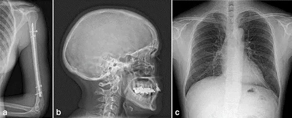
Fig. 1 Image examples of a an upper arm, b a skull and c a thorax a.p. acquired with an MRD1417 for general radiography (e-Join)
Basic operations that meet these requirements include
1) Dynamic range rescaling by an appropriate setting of the grey-scale window and level values. Segmentation techniques are used to remove unnecessary information by detecting the areas which are either subject to direct radiation or which are defined by the projected collimator. The resulting signal histogram, containing only the signal data of the object, is used to set appropriate window and level values or to extract other relevant information.
2) Grey scale mapping with non-linear characteristic functions to increase contrast in the region of interest while reducing it in other areas of lesser interest.
3) Dynamic range or density compression, defined in its simplest form by subtracting a given percentage of the low-pass filtered image (using very large filter kernels) from the original image. This technique allows one, for instance, to display the lung and the mediastinum of a thoracic image with high contrast. Similarly, this procedure lends itself to ideally display the chest wall and skin area of a mammogram simultaneously.
4) Edge enhancement, a filtration method which improves the fine details of objects by applying a small kernel high-pass filter to the original image.
5) Multi-frequency filter techniques are a more general approach and may combine contrast enhancement, resolution improvements and noise reduction at the same time in the appropriate areas of the image. Here, the image is divided into several spatial frequency domains. Optimized filters are used in each frequency band, before the image is reconstructed. In addition, the filter parameters may be linked to the local image signal which may further improve the presentation of the diagnostic image content to the radiologist’s eyes.
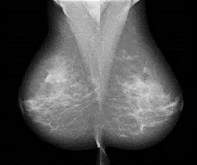
Fig. 2 Image examples of lateral mammograms acquired with MMD1012 (e-Join)
Valuable additional information may be gained when synthesizing several images into one or several new images. Image stitching is one such method which is used to create a new image larger than the detector area. Some of the applications, in particular full body scans of the upright standing patient, may require very fast consecutive image acquisitions because in most cases one is confronted with elderly and weaker patients. The flat detector’s capability to support fast repetitive image acquisitions plays an essential role in such a procedure. To this end, several consecutive X-ray exposures are taken of the object so that a small overlap area between two neighboring images exists. The overlapping areas of the X-ray exposures are used by the image processing software to create seamless junctions. In this way, the complete spinal column or the entire skeleton can be displayed via a composed image. Special orthopedic image processing software allows to accurately measure and diagnose bone defects.
Another technique is the dual energy method which takes advantage of the energy dependence of the mass absorption coefficient. Here, two X-ray images are gathered, using very different X-ray spectra. By adequate linear superposition of the images, different types of tissue may be displayed selectively. Again, flat detectors are ideally suited for this application as they allow acquisition of the two images within a very short time interval which helps to keep motion artefacts at a low level. In thoracic diagnostics, for example, the soft tissue (lung parenchyma, mediastinum) or the structures containing calcium (bone, calcifications) may be displayed separately. This method may prove advantageous for displaying tumors. Whether or not it will have a future is open-ended, since computed tomography represents a superior and well-established alternative for this kind of application.
Quasi 3D information can be achieved by digital tomosynthesis. With this technique one acquires a series of projection images (typically 10–30) in a given angular range (e.g. −20 to +20°). In a post-processing step these images are used to reconstruct the 3D data set, applying similar algorithms as the ones used in computed tomography. Here, though, the spatial resolution in the direction normal to the detector is much lower than in the directions parallel to the detector plane. Presently, the main focus of applications is on mammography with the goal to visualize the 3D spatial distribution of calcifications and to improve the detectability of masses. Other applications in general radiography may include the diagnosis of arthritis in finger joints or lung nodules.
In the future, CAD (computer aided detection) methods will play a more and more important role of feature extraction from individual images. One such application is the detection of tumors in thoracic images. To date, however, it is difficult to say how long it will take until established methods are available, especially in view of the complexity involved in detecting tumors in thoracic radiographs. For digital mammography, the breakthrough of CAD methods is closer to reality and may even accelerate its acceptance. CAD systems, known to supply consistent quality (parameters—humans are influenced by—such as the time of day or the workload, do not exist for such systems) have continuously shown improved sensitivity and specificity over the past years. Although this topic is still discussed controversially, there is no doubt that in taking the role of a “second opinion”, the technology very efficiently supports radiologists in their diagnosis.
New applications in angiography and fluoroscopy
Real-time X-ray imaging systems are used for a wide spectrum of clinical applications. Such systems range from mobile X-ray systems for surgery and over- and under table fluoroscopy systems (e.g. for examinations of the gastrointestinal tract) to angiography systems equipped for the diagnosis of vessel pathologies and minimally invasive treatment. Moreover, the field of angiography includes special systems for cardiology and neurology.
The image intensifier which has been the technology of choice for these systems has matured over the past decades allowing for high-quality X-ray examinations and interventions. The X-ray dose required for examinations or interventions was successively reduced, decreasing at the same time the X-ray exposure to both patient and user. Therefore, all new detector technologies are measured against the level of quality standard established by image intensifiers. However, image intensifier technology also has a number of disadvantages. The mapping of the convex input screen onto the planar output fluorescent screen leads to image distortions especially along the rim of the image and consequently to non-homogeneous image quality across the image. Scatter processes of light and electrons within the image intensifier limit the coarse contrast resolution (veiling glare). Yet another critical point with large image intensifier formats is patient access as well as the flexibility during angulation of the image intensifier at the C-arm due to the large size and depth of the vacuum tube. Also, the amplification principle of image intensifiers based on internal electric fields prohibits their usage in the vicinity of strong magnetic fields. Finally, large-format image intensifiers did not succeed in replacing screen-film bucky trays in fluoroscopy systems to cover radiography applications. The reasons for this being the round image format, the large depth of the image intensifier tube, and a limited DQE at the high exposure levels required for radiographic exposures.
Flat detectors for real-time imaging either avoid or at least reduce some of the disadvantages of image intensifiers. The most important technical advantages of flat detectors are summarized below:
1) Homogeneous image quality across the entire image area resulting in distortion-free images and position-independent spatial resolution.
2) High “low contrast resolution”.
3) High DQE across all dose levels, particularly for CsI/ aSi-based flat detectors.
4) High dynamic range, covering all dose levels from fluoroscopy to DSA.
5) Square or rectangular active areas which, together with the flat and compact design, improve the accessibility of the patient.
6) Compatibility with environments where strong magnetic fields are required.
These advantages suggest that X-ray systems with flat detectors have the potential to improve further the existing applications and give way to new diagnostic and interventional techniques. The following three examples shall underline this statement.
The improved detectability of small structures such as the tip of the catheter due to increased contrast resolution may lead to shorter examination times. This in turn should reduce the integrated applied dose. In cardiac angiography the improved visibility of stents allows, for example, to use hand injections of contrast medium for left ventriculograms, which reduces the contrast medium load for the patient.
3D views of body regions generate additional information for diagnosis and facilitate orientation during interventions. Today 3D visualization is a standard feature for interventions in neuroradiology. The treatment of aneurysms and arteriovenous malformations through coils or other embolization methods has been in use for years, using image intensifier-based X-ray systems. These methods, however, will largely benefit from flat detectors due to the rectangular image format, the high spatial resolution, and the distortion-free images. The high dynamic range and the good contrast resolution will enable to enhance the soft tissue resolution and may allow to probe into some of the classic applications of computed tomography.
The flat detectors’ compatibility with strong magnetic fields supports magnetic catheter navigation which is a unique new technology platform for electrophysiology and interventional cardiology. With the help of two magnets, providing a magnetic field of up to 0.1 Tesla, the clinician can accurately navigate catheters and guidewires through the vessels and the chambers of the heart. Rotating the magnets independently changes the local magnetic field at the position of the catheter whose tip is equipped with a tiny magnet. As a result, the catheter changes orientation into the desired direction within the vascular tree. The guiding is supported by the flat detector which is used to acquire two perpendicular X-ray projection images showing the catheter and the vessel structure. By drawing the new intended direction of the catheter directly onto the projection images, the new required local magnetic field can be calculated and set up by moving the magnets into their new positions. This allows to perform difficult navigation tasks such as moving along a calcified vessel which can now be performed with softer catheters minimizing the traumatization of the vessel, changing direction at a bifurcation (in particular if the branch point itself is stenosed), or other hard-to-navigate sections in the vascular or cardiac system.
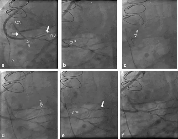
Fig. 3 Highly symptomatic patient with three stenoses beyond a previous vein graft in the right coronary artery (RCA) and associated vessels. Angiograms acquired with an AXIOM Artis dFC Magnetic Navigation (Siemens). a Angiography with all three lesions identified: (1) at graft anastomosis, (2) in the posterior lateral artery (PLA) and (3) in the RCA very close to the bifurcation. b Wire turning retrograde into RCA out of veingraft. c Wire bending from RCA into acute marginal branch without removing wire for reshaping. d Wire anchored in acute marginal branch. e Balloon at third lesion in the RCA very close to the bifurcation. Wire anchored into distal acute marginal branch. f Post-PTCA of all three lesions.
This method may revolutionize the work of cardiologists and radiologists in the near future. Several applications are in the focus of interest. One problem which can be addressed with the new technology is the chronic blockage of the cardiac vasculature, which so far has always fallen into the domain of cardiac surgery. With the new system, opening the chronic total occlusion may be addressed without surgery. Figure 3 shows a case of a highly symptomatic patient with three stenoses beyond a previous vein graft in the right coronary artery and associated vessels. That patient was treated by magnetically guided PTCA (percutaneous transluminal coronary angiography) of the three stenoses in the right coronary artery. Another disease to be addressed is complex arrhythmia, such as fibrillation in the left atrium. Here, the system is used to apply radiofrequency ablation of the arrhythmogenic tissue in the atrium. A further area of focus is in the field of serious cardiac insufficiencies where pacemakers are used to stimulate both chambers of the heart. With this new technology, present problems to navigate the probe electrodes into the optimum positions through the veins may be overcome. An even other field may be applications where medical devices such as drug-eluting stents need to be placed at small and tortuous side-branches, requiring support by magnetic assisted navigation.