
To characterize the performance of X-ray detectors in a transparent and reproducible way, a variety of physical measures have evolved. The most important performance parameters are (1) dynamic range, (2) MTF (modulation transfer function), (3) DQE, and (4) image lag. These high-level parameters are fundamentally governed by a large set of lower-level design and material parameters of the detector. Figure 1 shows an example of a flat detector specifically developed for general radiography. This detector with an indirect conversion process is based on a CsI scintillator. With its active area of 43×43 cm2 it is the largest of its kind and covers the most demanding sizes such as thorax and pelvis. The pixel size of 139×139 μm2, optimized for high resolution required in radiography, leads to a square matrix of about 9 million pixels.
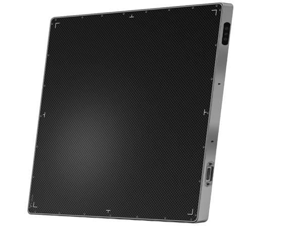
Fig. 1 Flat detector for radiographic applications with an active area of 43×43 cm2 and a pixel size of 139×139 μm2 (MRD1717, e-Join, China)
Dynamic range
Dynamic range is one of the key parameters characterizing the performance of X-ray detectors. The flat detector shown in Fig. 1—applying several 16-bits ADCs—exhibits very low electronic noise at a level of less than 1 digital unit. It shows a linear response as a function of dose (Fig. 8) and begins to saturate at a dose level of about 64 μGy. This allows a large dose range to be covered without the need for detector internal amplifier gain changes. Hence, the detector may not only be used at a standard dose level of 2.5 μGy (equivalent to 400 speed) but also at higher dose levels if highest image quality with respect to stochastic noise is required and at reduced dose levels (e.g. by 50%) which were demonstrated to be adequate for skeletal radiography. Even much lower doses were shown to be useful for specific purposes such as the control of implants or search for foreign bodies. Figure 2 also shows the response function for a screen-film system. Compared to the flat detector, its range of linear response is rather limited. This comparison demonstrates the advantage of flat detector technology over the conventional method since a much larger dose range can be addressed without risking wrong exposures. This feature reduces the need for retakes substantially which is particularly handy if external dose sensing devices are not available, for example in case of free exposures. A word of caution, however, is necessary, as the large dynamic range implies the risk to deliver higher dose to patients than necessary. Therefore, it is mandatory to optimize the procedures in such a way that the right image quality is provided at the lowest possible dose.

Fig. 2 Signal response of (1) a flat detector for radiographic applications with 16 bits analog-to-digital conversion and of (2) a screen-film system. For comparison, the electronic noise level of the flat detector is indicated as well
In vascular imaging or cardiac angiography, an even broader dose range needs to be covered, ranging from very low system dose levels of about 10 nGy in fluoroscopy to much higher system dose levels of about 5 μGy in DSA (digital subtraction angiography). The need for this large dynamic range can be met by providing several detector internal modes, each one with a different amplification level at the input stage. The wide range of dose requirements is covered by selecting the detector mode which is appropriate for the expected signal range of the respective application.
Modulation transfer function
The MTF describes the detector’s ability to transfer the input signal modulation of a given spatial frequency to its output. When defining the modulation of a digital (pixelized) detector one needs to take some care, as the measured modulation depends on the phase shift between the input signal and the pixel grid. Ambiguities are avoided by defining the pre-sampling MTF, i.e. the modulation before sampling but after convolution of the analog signal with the discrete sensor structure. The limiting function of a sensor of finite size is given by the Fourier transform of the pixel aperture at: “F(f)=[sin(Πaf)]÷[Πf]= a×[sinc(af)]” commonly referred to as the “sinc-function”.
Figure 3 shows typical presampling MTFs for different technologies used in general radiography. The MTFs for screen-film systems and storage phosphor systems exhibit similar values over the spatial frequency range. Indirect converting flat detectors, based on CsI, show an improved MTF, particularly at higher spatial frequencies. Due to some degree of light scatter in the CsI the response function stays below the limiting sinc-function. This built-in low pass behavior has some advantages as described below. That feature applies to a much lesser extent to direct converting detectors based on a-Se where the applied electric field forces the generated charge to be almost completely collected in the one pixel below. Consequently, the MTF may come closer to the theoretical limit.

Fig. 3 Typical pre sampling MTF curves for different X-ray detectors used in general radiography applications: (1) flat detector with indirect conversion based on CsI, (2) flat detector with direct conversion based on a-Se, (3) storage phosphor with standard resolution and (4) screen-film system
One important aspect of screen-film systems is that each sensitivity class (speed) matches a specific dose range. Increasing film speed, however, goes along with reduced resolution. This feature does not apply to flat detectors as their spatial resolution is—within their linear range—independent of the applied dose level.
Another important parameter of a digital imaging system is its limiting resolution. It is given by the Nyquist frequency, defined as 1/2d where d is the distance between two neighboring pixels. It represents the upper frequency limit at which spatial structures can be detected and above which aliasing effects occur. Aliasing not only effects the signal but also the noise. Hence, a MTF which does not reach the limit given by the sinc-function acts as a built-in low-pass filter. This is the case for the most frequently used scintillators such as CsI and Gd2O2S. The advantage is that aliasing and therefore back-folding of noise from the frequency region beyond the Nyquist frequency is partially suppressed—an important aspect to reach high DQE values at high spatial frequencies.
Detective quantum efficiency
DQE has become one of the fundamental physical parameters related to image quality. It refers to the efficiency of a detector to convert the X-ray radiation signal at its entrance window into a useful image signal. By definition, DQE compares the SNR (signal-to-noise ratio) at the detector output (digital signal) with that at the detector input (X-ray flux at the entrance window) as a function of spatial frequency f: DQE(f)=[SNR2(f)out]÷[SNR2(f)in]=[q2G2MTF2(f)] ÷[ NPS(f)]
DQE(f) is derived from the measured quantities MTF(f), noise power spectrum NPS(f), detector gain G, and the calculated average input quanta per unit area q. Since the SNR at the input corresponds to that of the ideal detector, DQE can reach a maximum value of 1.0. In practice, however, DQE is limited by the energy dependent quantum efficiency of the X-ray conversion layer.
Figure 4 shows DQEs for the most frequently used technologies in general radiography. Screen-film and storage phosphor systems reach values between 20 and 30% at spatial frequencies below 1 lp/mm. Compared to screen-film, however, storage phosphor systems show a much more rapid fall-off at higher spatial frequencies. Higher DQE values are reached with direct converting flat detectors based on a-Se. The highest DQE values, however, are obtained with indirect converting flat detectors based on CsI. Observer studies demonstrate that the high DQE values reached with the indirect converting flat detectors based on CsI correlate with (1) superior image quality (provided comparable system conditions are given), and (2) the potential to reduce dose without loss of image quality, when compared to other technologies.

Fig. 4 DQE values of different X-ray detectors for general radiography: (1) flat detector with indirect conversion based on CsI, (2) flat detector with direct conversion based on a-Se, (3) storage phosphor with standard resolution and (4) screen-film system
DQE is largely governed by the absorption properties of the converter material. Therefore, it is worthwhile to briefly review the most commonly used X-ray converter materials for flat detectors in that respect. In what follows, quantum efficiencies are calculated for a CsI layer of 600 μm and an a-Se layer of 1000 μm (the thickest layers which have been reported for a-Se). Furthermore, a filtration of 4 mm Al and 0.2 mm Cu and a simulated object of 200 mm of poly (methyl methacrylate) are assumed. At 70 kVp quantum efficiencies of 77 and 67% are reached for CsI and a-Se, respectively. At higher peak voltages such as 120 kVp—typical for thoracic imaging—the relative advantage for CsI is even more pronounced. Here, quantum efficiencies of 52 and 37% are reached for CsI and a-Se, respectively.
In fluoroscopic imaging conditions very low signals have to be detected. The signal competes against the statistical noise as well as the additive electronic noise of the imaging chain. Hence, high absorption as well as high gain are essential under these circumstances. As these properties are in favor of CsI, this material qualifies particularly well for fluoroscopic imaging.
At the low end of the clinically relevant X-ray spectrum, a-Se has better absorption properties than CsI. This makes a-Se the ideal detector material for mammography, leading to the highest DQE. This statement is reflected by measurement results for two flat detectors, currently available with these two competing X-ray conversion materials. A detector based on a-Se/a-Si—featuring a pixel size of 70 μm which corresponds to a Nyquist frequency of 7.2 lp/mm—exhibits significantly higher DQE values over the whole spatial frequency range than a detector based on CsI/a-Si which has a pixel size of 100 μm, corresponding to a Nyquist frequency of 5 lp/mm.
Image lag
Image lag (sometimes called memory effect) may cause an increase in dark current and cause a reminiscent image after exposure. This phenomenon results from the release of charge after the termination of the X-ray exposure: the charge which was trapped in metastable band-gap states in the a-Si active matrix or a-Se converter material during exposure is released afterwards slowly over time. Hence, lag is usually measured in subsequent non-exposed images as a function of elapsed time after an exposure or a series of exposures. The lag requirements on flat detectors built for real-time applications are high, as such detectors have to switch from high dose operations (e.g. DSA) to fluoroscopic dose levels within a very short time interval of about 1 s. As of today, the lowest values for lag are reached with the indirect converting flat detectors.
For a CsI/a-Si-based indirect converting flat detector designed for cardiac angiography—similar in technology as the one shown in Fig. 1—lag is measured to be about 0.3% after 1 s and below 0.04% after 10 s, using a detector mode with an integration time of 15 ms.
In comparison, lag values of about 6% after 1 s and around 1% after 10 s are reported for a direct converting flat detector based on a-Se/a-Si, applying similar integration times of 20 ms. Such a high level of lag not only makes recursive offset subtraction methods necessary which may cut the effective frame rate of the system in half as every second frame is used for offset update. It also reduces the available dynamic range.